EQ Part 2

EQ Pt.2 - Transformerless Mics
Friday, February 7, 2014
The most common circuit found in inexpensive condenser mics is a variation of the Schoeps impedance converter. It consists of a FET input stage, T3, which buffers the very high impedance of the capsule and also serves as a phase splitter to drive a pair of emitter follower transistors, T1 & T2, which provide enough current gain to drive the low impedance balanced mic cable. Here’s a typical example, the MXL 990 as reverse engineered and posted on the internet. The capsule bias oscillator has been omitted, since it isn’t part of the discussion.
Not all microphone capsules are flat. Sometimes they need electronic equalization.
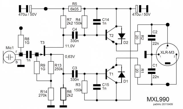
As MXL ships them, the electronics have a flat frequency response above a low frequency rolloff point established by C3 and C4. A common modification is to increase C3 & C4 to somewhere between 0.47 and 1 uF each, lowering the bass rolloff point. C14 and C15 set a high frequency rolloff point well above the audio range to eliminate possible ultrasonic and RF instability.
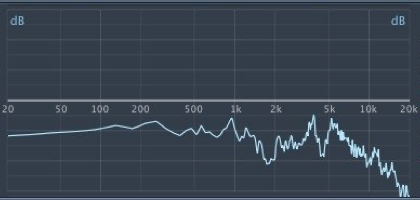
A lot of these inexpensive condensers have capsules copied after Neumann’s U87, which has a peaked response in the high frequency region around 10 KHz. The copies often have a much narrower and higher peak than the real thing, and coupled to the flat electronics with rolled off low end, the mics sound thin, sibilant, and screechy. Neumann compensates for the capsule’s HF rise by rolling off the top end of the electronics with negative feedback. This isn’t as easy with the Schoeps topology because the circuit is essentially all unity gain followers. There is a theoretical 2:1 gain because T3 produces two signals of opposite phase, but as far as voltage goes, the signal out at the XLR pin 2 is identical to the signal at the gate of T3, and the signal at pin 3 is an inverted copy.
Since we don’t have a much larger out-of-phase signal anywhere to drive a negative feedback loop, we can’t easily copy Neumann’s solution to the zingy capsule.
A popularly suggested cure is to increase the capacitive load on the FET’s drain, that is increase C14, or add an additional cap across R7. That works, but not well. For one thing, it rolls off highs at XLR pin 3, but it also boosts highs at pin 2, and of course it unbalances the output signals. This may or may not cause big problems depending on the common mode response of the following preamp input, but it’s probably bad practice.
OK, so increase both C14 and C15. That restores balance. But. It has the undesirable effect of slew rate limiting T3, and causing lower clipping limits on fast transients and slower recovery from overloads. Same goes for adding a capacitor between the bases of T1 and T2.
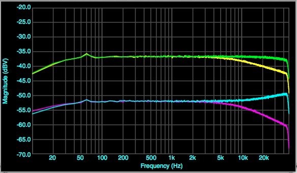
Here we see what happens changing only C14. Green = C14 = C15 = 470pF (stock config.)
Yellow = C14 = 5600pF, C15 =470pf, measured between pin 2 & pin 3 (balanced input)
Cyan = C14 = 5600pF measured at pin 2 to pin 1 (non-inverting output)
Magenta = C14 = 5600pF measured pin 3 to pin 1 (inverting output)
As you see, we get less rolloff than expected because while pin 3 rolls off at 6dB/octave, pin 2 actually rolls UP at half that rate. Our balanced output isn’t.
One simple solution is to separate the rolloff caps from T3 by a couple of series resistors between C3 and R3/C15/T1, and C4 and R4/C14/T2. That lets T3 work, and establishes a stable resistance for the capacitors to work against. The HF response depends on a simple single pole RC network. A good value for the resistors is around 10K Ω.
This page is getting a bit long, so the story continues on the next page.