One More BM-800 Circuit board

Still another BM-800 Circuit Board
Sunday, December 6, 2020
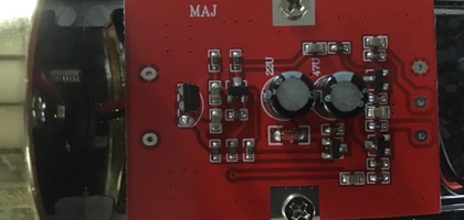
Steve found another version of the BM-800 circuit board in his mic. This one is also missing the handy solder pads at the top of the board, so we have to solder our large electrolytic filter cap to one end of surface mount resistors and a handy nearby ground. I’d tin the positive lead of the cap, lay it alongside the resistors, and quickly melt the solder just enough for a connection. Too much heat, and the resistors will come loose at both ends. A bit of tricky soldering.
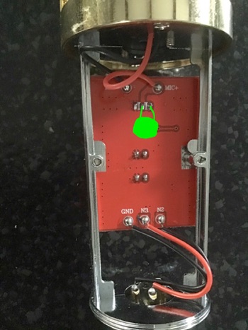
The small ceramic cap is easier to mount on the back side of the board, tacked directly to the pads for the FET. Something like this:
Steve found another printed circuit board with the exact same circuit in his BM-800.
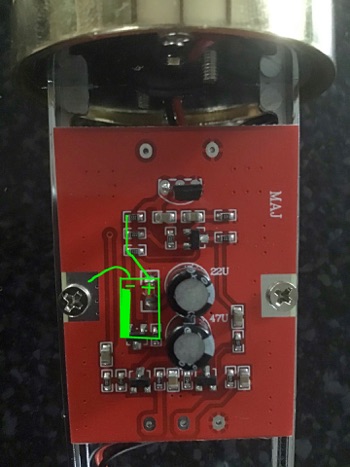
The electrolytic cap can be anywhere from 220 to 1000 uF at 16 V or more. It needs to be small enough to fit into the mic. You could flip this PCB over for more height if needed.
The small NP0 or C0G ceramic cap can be 10 to 40 pF at 16 V or higher. With a larger capsule, these mics are too loud. The small cap reduces the volume and distortion. The larger the cap, the quieter and less distortion. 22 or 27 pF works well for me.
You may need to swap the wires connected to pads N2 and N3 if your BM-800 is out of phase with your other mics. Most BM-800s are.

