Schoctava, a simple mic circuit

Schoctava, a simple mic circuit
Sunday, May 7, 2017
While investigating John Bierman’s modified Octava, the Lika mic (see here), it occurred to me that if you stacked the two stages with the output PNP “on top” you’d have something sort of like half of a Schoeps. I sketched it out and set it aside, but I kept going back to look at it, and couldn’t see why the idea wouldn’t work. It simplifies both circuits. Gets rid of the electrolytic output capacitor and simplifies the biasing of the capsule and transistors as well. Hmmm...
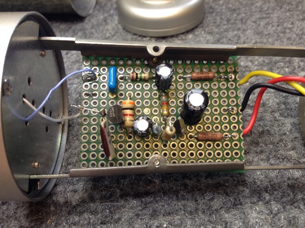
So a couple of days ago I built one on a scrap of perf board, fooled around with the transistor bias resistors, and generally figured out what had to be where for the thing to be stable and have the transistors in reasonable parts of their characteristic curves. The result so far is an FET, a PNP, 8 resistors, and 6 capacitors. Few parts, no really expensive components, and easy to fit onto a single-side circuit board. The 1 Gohm resistor is the most exotic part.
How simple can we make a high quality mic circuit?
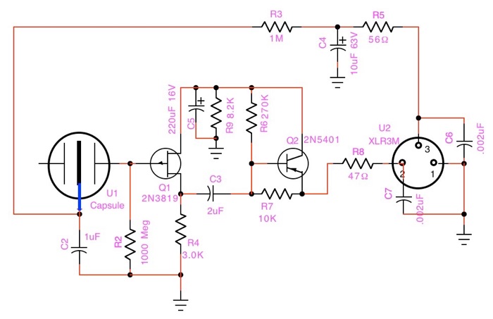
Not a lot to it, is there? On to the circuit diagram and theory of operation:
This version is for a “true” condenser capsule.
For an electret capsule, delete R3 and C2 and connect the capsule straight to ground and the FET.
C6 & C7 RF bypass caps mounted on the XLR connector.
All resistors 1/4W 5% or better.
C6 & C7 NP0 ceramic. C2 monolithic ceramic 50V. C3 is the only cap directly in the signal path. Use your favorite film or other type.
The first thing you notice is like the Octava, only pin 2 of the output is actively driven. R5 provides a matching impedance on pin 3 to maintain common mode hum rejection in the mic cable. C4 grounds pin3 for audio, but passes the full phantom power voltage on to provide bias for the capsule. The capsule is directly connected to the gate of Q1, which operates as a source follower with no voltage gain, but brings the impedance down to about 1Kohm. C5 provides AC ground for the drain. C3 couples the signal to the second stage emitter follower Q2.
Q2 also provides no voltage gain, but amplifies current, thus bringing the impedance down again by a factor equal to its beta. The impedance at the emitter of Q2 is around 10 ohms, and R8 matches that to R5 and the roughly 110 ohm impedance of a typical 2 conductor shielded cable. R6 & R7 provide base bias for Q2. R9 provides a discharge path for C5 and allows Q2 to run more current than Q1. There is some leeway in parts values. I chose these because they were on hand. That’s all there is to it.
Onward then, to measurements! First, frequency response measured with white noise:
-1dB @ 40KHz. Can’t complain about that. C5 sets the LF -3dB point to 20Hz. Make C5 bigger to extend LF. Make C3 smaller if more LF rolloff is desired, maybe .01 - .02uF for a vocal mic.
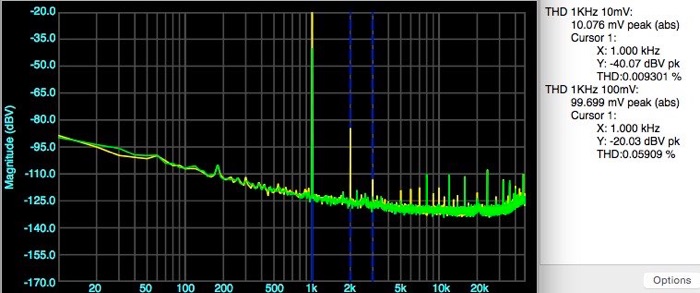
Total Distortion at 1KHz, 10 mV 0.009% (green), and 100 mV 0.06% (yellow) looks good. 3rd harmonic is low. Tiny amounts of higher order harmonics @ 5, 6, 7, etc. Digital artifacts @ 8, 12, 16, 24... fractions of 96KHz sample rate are computer related, not mic distortion.
I’ve tried different FETs and PNPs in the prototype and they all work, some better than others. The types shown are what the circuit was designed around. To sum up, this simple circuit performs as well as most professional studio mics in typical usage. It puts the full 48V on the capsule. It works well with modern capacitor-coupled preamp inputs, but the DC imbalance may be problematic with older transformer-input preamps. It might be a bit challenged driving 100 meters of mic cable in a large concert hall, but if you’re recording at Carnegie Hall, you probably can afford any mic you want. Now to build a couple more and use them in the real world.
News! Robert at Russell Technologies has been tinkering with the circuit too, and has worked out a variant. He has laid out a printed circuit to fit the MXL 991 mic. Check it out. I plan to try his version too. Watch for updates.
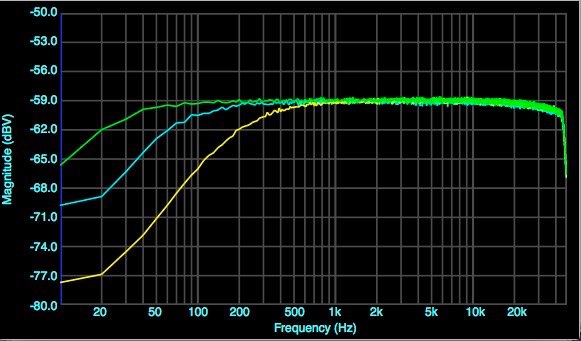
C3=1uF
C3=.022uF
C3=5600pF

