Mic EQ Pt.3

EQ Pt.3 - Transformerless Mics
Saturday, February 8, 2014
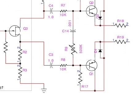
As mentioned in the previous article, one simple way to implement a high frequency roll off without messing up the FET is to insert a resistor between the FET coupling capacitor and the HF bypass capacitor. Here we have inserted 10K resistors in series with C3 and C4.
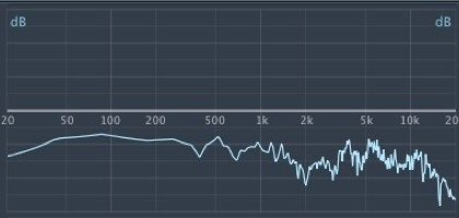
Not all microphone capsules are flat. Sometimes they need electronic equalization.
Here you notice two things.
First, C14 & C15 between base and collector of Q1 & Q2 are gone. R7 and R8 along with the intrinsic input capacitance of the transistors serve to damp any instability above 40KHz.
Second, now C14 connects to a variable resistor to the opposite base. Yep, it’s an old fashioned treble control. C14 sets the turnover frequency, and R9 sets the slope.
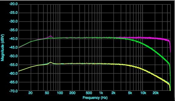
Now we have something like this, as the variable resistor R9 increases, the slope decreases, flattening earlier, and the inflection point also changes slightly. We should be able to darken or brighten the mic to taste, though. Probably not wise to mention this to any intern helping out around the studio, or she’ll be fiddling with the mic constantly.
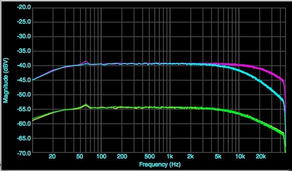
Magenta = C14 & C15 = 470pF Notice the 3dB point is now about 20KHz.
Cyan = C14 & C15 = 1500pF. Steeper slope, suited to capsules with 12-13KHz peaks.
Yellow & green = C14 & C15 = 1500pF measured between pin2 & pin1 and 3 & 1. Note that both roll off at 6dB / octave as expected.
Now we make a further change: we replace the two capacitors with a single cap from the base of Q1 to the base of Q2. This should remain balanced, and sure enough it is.
Magenta = no capacitor. Note rolloff beginning at 30-40KHz due to transistor capacitance.
Green = C = 1000pF, balanced out pin2 to pin3.
Yellow & cyan = C = 1000pF, pin1 to pin2 and pin1 to pin3, equal and opposite phase.
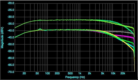
Another change: we add a resistor in series with the cap. Now our circuit looks like this:
Yellow, C14=1000pF, R9=0. Cyan, R=5KΩ. Green, R=10K. Magenta, R=25K. Grey, R=100K
Upper curves C14=470pF, R=0 and R=25K. Now, about noise . . .