In Which Mic Capsules Play Musical Chairs

Omni Pattern for A Perception 220
Saturday, March 16, 2013
I had put double-sided K67 type capsules in a pair of upgraded MXL 990s where only one side was connected. I decided to move those capsules to my AKG Perception 220s and re-purpose the -20 dB pad switch as a pattern selector. I don’t like the sound of the P220 with the pad engaged, and an omnidirectional pattern would be a nice addition to the mic. So the 35mm Alctron 6 micron capsules went into the AKGs and the AKG capsules went into the MXL bodies. The junk box held an AKG 451 body and a CK-5 capsule with a split diaphragm, so I mounted one of the leftover MXL 990 small capsules into the CK-5 shell.
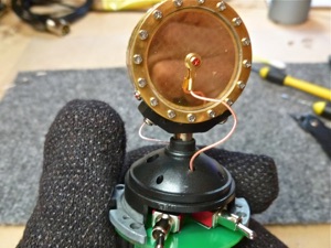
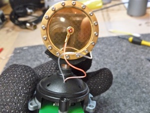
First, putting a double-sided capsule into a Perception 220:
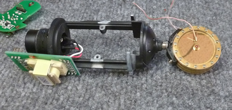
Disassemble the mic, and unsolder the wires to the capsule at the FET board. Undo the two screws which hold the capsule to its saddle, and install the new capsule in its place, as seen above.
I decided to swap some capsules around.
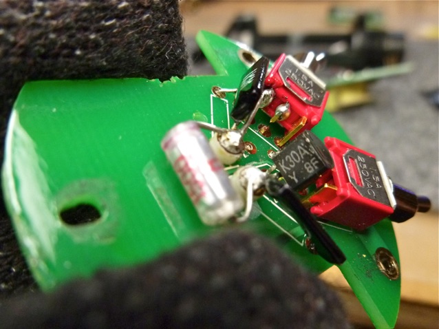
Turning our attention to the FET input board, we will replace the 470 pF input coupling capacitor with a film type, remove the 560 pF pad cap, and cut 2 of the pins on the pad switch. These pins will connect to the very high impedance mic capsule, so they will be isolated from the PC board.
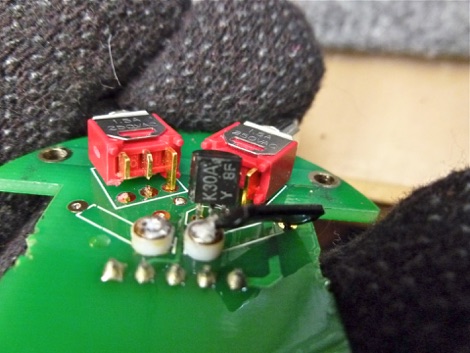
With parts removed, the board looks like this. The hardest part is snipping out small sections of switch leads. Small nose wire cutters are required. The 1 G ohm resistor will be reinstalled. It was removed for access to the switch.
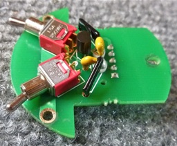
With a new film capacitor and the resistor reinstalled, a wire is soldered from the input terminal to the cut outer lug of the switch. Now we’re ready to attach the wires from the capsule and reassemble the mic.
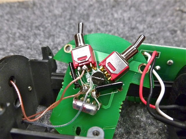
The backplate wire goes to the same hole on the PC board as before and the front diaphragm wire goes to the same standoff terminal. The wire from the back diaphragm goes to the center terminal of the switch. The switch connects the back diaphragm either to backplate (cardioid) or to the front diaphragm (omni).
Front
Back
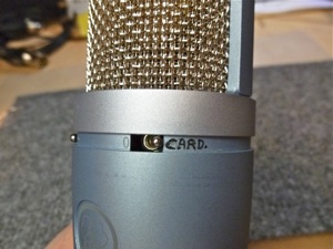
The last little job is a label for the switch. Could be neater, I admit. Sound sample here.
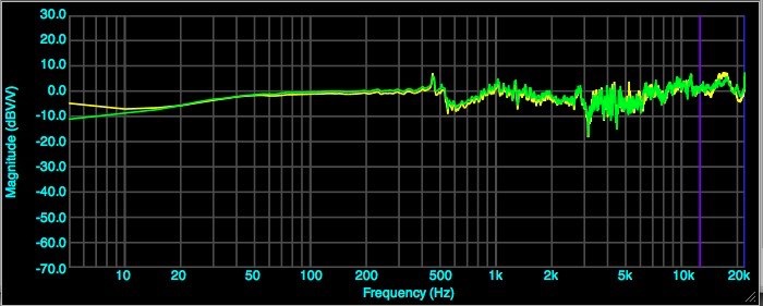
Finally, quick frequency sweeps.
First, omnidirectional, 2 mics.
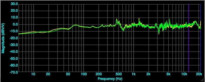
Second, cardioid, 2 mics.
5 Hz resolution, no smoothing.