Inside a ’67 Style Capsule

“K67” Capsule Take-apart
Tuesday, February 19, 2013
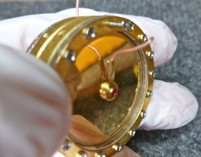
Ever wonder what’s inside a microphone capsule? The mysterious heart which transforms sound to electricity? I took the capsule from an inexpensive Chinese Alctron microphone apart. It’s a supposed copy of the Neumann K67 capsule as used in several famous mics, and these copies are found in many of the inexpensive Large Diaphragm Condenser mics on the market. There are variations in the details of construction from one brand to another, but the backplate which is the heart of a mic is usually copied from the K67. This is perhaps unfortunate, because the original Neumann design produces a high frequency resonance which is corrected in the electronics. Most inexpensive mics use electronics with a flat frequency response copied from a Schoeps mic, resulting in an overall peaked response.
This capsule, like most LDCs, is made in two halves, each of which has a diaphragm and backplate, bolted back to back, with a thin air chamber between them. The result is essentially a pair of cardioids back to back. Each half-capsule acts as an acoustic delay line and low-pass filter for the other half. In some mics, only one diaphragm may be connected, giving a cardioid-only mic. If both diaphragms are connected in parallel, the result is an omnidirectional mic. If the two sides are combined out of phase, a figure-8 pattern results.
How is the most popular large diaphragm mic capsule built?
We take one apart.
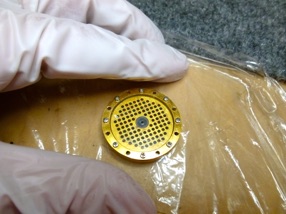
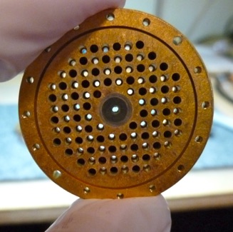
The ’67 backplate is characterized by a rectangular grid of holes. From the diaphragm side, there are rows of 6,8,10,12,12,12, 12,12,12,10,8,6.
Some of the holes are blind and establish the “air spring” behind the membrane. Some are drilled through at a smaller diameter to form the acoustic
resistance part of the delay line needed for a cardioid pattern. The grid pattern is easy to program into a CNC drilling machine, making this a fairly simple design to produce. All the holes are the same diameter.
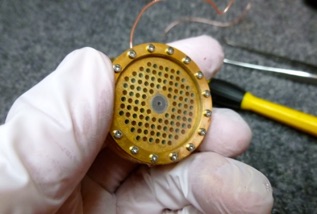
Two of the holes around the circumference aren’t tapped, and are drilled large enough for a screw to pass through. Removing the long screws from each side allows the halves to separate.
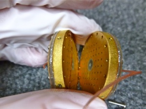
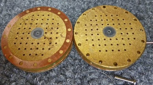
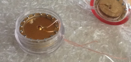
Notice that the two backplates are identical but are rotated 90°from each other so that the through holes don’t line up. Each hole in one meets land in the other. A copper spacer establishes the air volume in between.
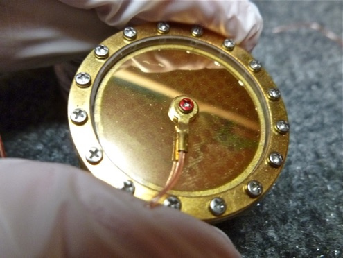
If you’re thinking of trying this with one of your mics, this is as far as you can go non-destructively. The diaphragms are NOT glued to the clamping rings, and loosening the clamp screws will release the tension on them, rendering them useless. But curiosity killed this cat, so onward . . .
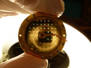
As noticed earlier, only some of the holes are drilled through. It turns out, every other hole is drilled, so half go through with a smaller drill, and half are blind. All the large drill holes are the same depth, and of course all the small drillings go through, again simplifying tooling setup.
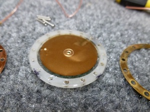
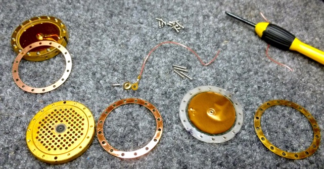
The parts of our half-capsule from inside to out, left to right are the backplate, the diaphragm spacer, the diaphragm, a plastic clamp ring, and a brass clamp ring. The diaphragm is covered with gold only on the outside, so if it hits the backplate, it won’t short out.
Now we know what’s inside a typical screwed-together mic capsule. To salvage the capsule, making use of the intact half, I put a plain plastic diaphragm on the side I took apart. With the plastic stretched outside the clamp ring, I could hold it in tension while tightening the screws. When assembled with the good half, it should be usable as a cardioid-only capsule, though most likely not a very good one. OTOH, this was a disposable capsule to start with.