Measuring the Spamplifier

Measuring the Spamp
Monday, March 15, 2021
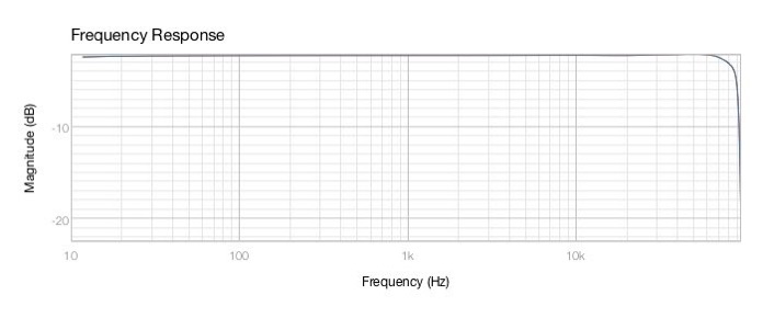
Finally got around to measuring the Spamplifier’s response and distortion. As expected, not much to write about; not much found. It’s clean.
Frequency response is flat as the computer interface, a MOTU M4 at 192KHz using the fixed gain channels 3 & 4 unbalanced outputs and unbalanced input via an RCA-to-TS phone adapter.
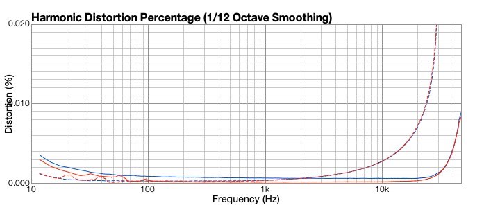
Distortion is likewise hard to measure at 1V output.
The upper line is third harmonic, lower line is 2nd harmonic; red is the Spamp and blue is the M4’s distortion with a loopback cable directly from output #4 to input #4. Really no difference. A straight wire with current gain, or maybe a straight wire with an input impedance of 8K ohms and an output impedance of 0.1 ohm.
Pretty graphs above are from Fuzzmeasure software from RØDE, the microphone guys. Fuzzmeasure and ElectroAcoustic Toolbox give the same results, but have different strengths. Sometimes I’ll use one, sometimes the other from now on, depending what I’m measuring.
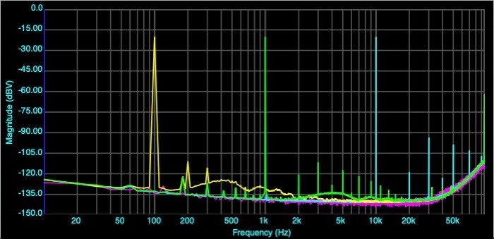
Here’s what distortion measurements look like from Faber ElectroAcoustic Toolbox (FEAT for short).
Yellow = distortion @100Hz, green = 1KHz, blue = 10KHz.
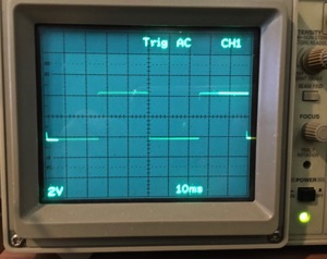
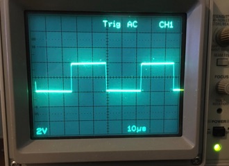
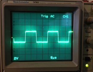
Square wave response:
I think I mentioned it’s a really sweet headphone amp? It makes some headphones that aren’t so hot driven directly from an iPhone sound much better. Others are a lost cause, but at least now I know it’s the headphones themselves I don’t like. Can’t blame the amplifier for not having enough drive, or having audible distortion.
With the wide bandwidth and low distortion it is a useful piece of lab gear as well.
20 Hz
20 KHz
50 KHz

