4-Channel Class-D Amp

Sure Electronics “4 x 100 W” Kit
Monday, April 30, 2012
Parts Express 320-302. From the catalog, quote:
4x100W @ 4 Ohm TK2050 Class-D Audio Amplifier Board
Based on two TC2000 and four TP2050 chips from Tripath, this Class-D audio amplifier board simplifies the creation of exceptional sounding custom multi-channel systems. Compatible with power supplies ranging from 10V-30V, it can be used in many audio applications. The amplifier has four channels with the same power of up to 100 watts each, resulting in outstanding sound quality and versatility. You can employ any number of channels you like, and leave the others unused. The amplifier is exceptionally well designed, with a lot of power reserve, high fidelity, low distortion, good S/N ratio, high sensitivity, low consumption, and full protection. These ideal characteristics make this amplifier a candidate to become the basic building block of your future high fidelity system, or it can become the element that will upgrade an existing system.
Specifications: • Output power: 30W x 4 @ 6 ohms (<1% THD+N), 40W x 4 @ 8 ohms (<3% THD+N), 100W x 4 @ 4 ohms (<10.0% THD+N) • Frequency response: 20 Hz to 20 kHz (±3 dB) • Signal to noise ratio: 100 dB (A-weighted) • Power supply range: 10V to 30V, maximum 32V • Dimensions (mm): 148.3 L x 134.6 W x 31 H.
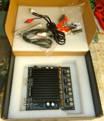
In the Box
is the amp board itself, two stereo headphone-to-RCA cables, four pieces of heavy hookup wire, and eight banana terminal posts (4 red + 4 black).
The board is 5.7” x 5.7” and a bit over an inch high without the terminals installed.
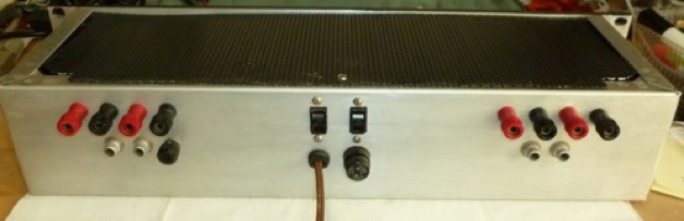
There are RCA input jacks as well as screw terminals for inputs. There are also screw terminals for speaker outputs and power input and ground. Power may also be supplied via a barrel connector, center pin +.
Every now and again a new kind of amplifier comes along. The latest major development is Class-D, or switching amps.
Class-D is basically a switch-mode power supply whose reference voltage is an audio signal.
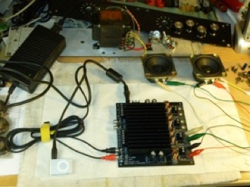
A quick check-out with iPod, a 12V laptop power supply, and clip lead speakers shows all 4 channels are working, and the voltmeter shows offset voltage at the speakers is safe, though above spec at 5mV, 113mV, 24mV, and 118mV.
Building Into a Chassis
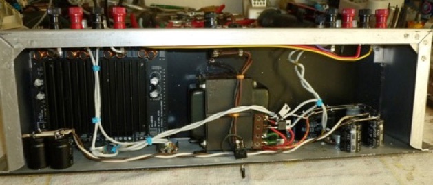
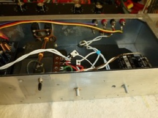
I built the amp into a Bud rack chassis with parts scrounged from old projects and my parts bins. The power transformer came from an old amplifier, 40VCT @ 5A and 6V @ 2A, yielding 28V DC.
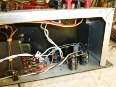
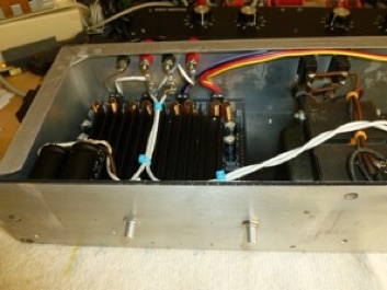
A pair of fast Schottky diodes rectify the AC and feed a bank of capacitors made of various brands and sizes totaling 42,000mF, attached to some buss bar and glued to the front panel. The variety of caps should help cancel any resonances and inductive reactances.
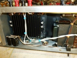
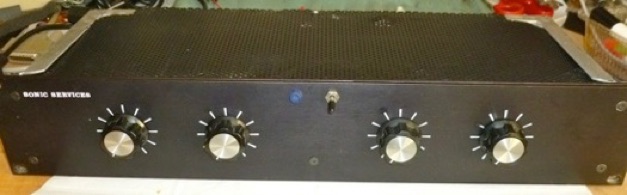
10K volume pots come from Radio Shack. Major parts are mounted to a used panel with drilled and tapped holes. The chassis is not deep enough for the board, so I cut off the back ½” for the speaker terminals with a Dremel tool after careful investigation to be sure nothing else was back there.
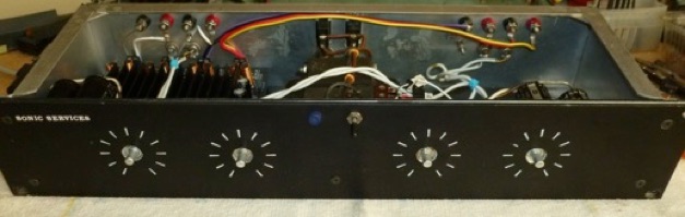
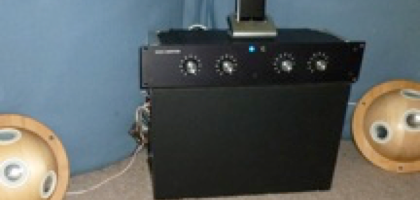
With everything attached to the structural front panel, I drilled, lettered, and bolted a dress panel over it.
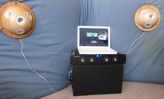
Ta-Daaaahhhh! Time to grab the laptop, some 24/96 hi-def music from HDTracks, hook up the hemi “Pseudo Point Source” speakers and passive subwoofer for a serious listening session.
Mods & Tweaks
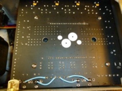
Since the amp board is mounted in a chassis, I removed the RCA jacks and cut off the back part of the PCB where screw terminals would mount. The board is mounted to the front panel on L brackets with nylon washers on both sides of the board, since there are traces which cannot be shorted to ground close to the screw holes.
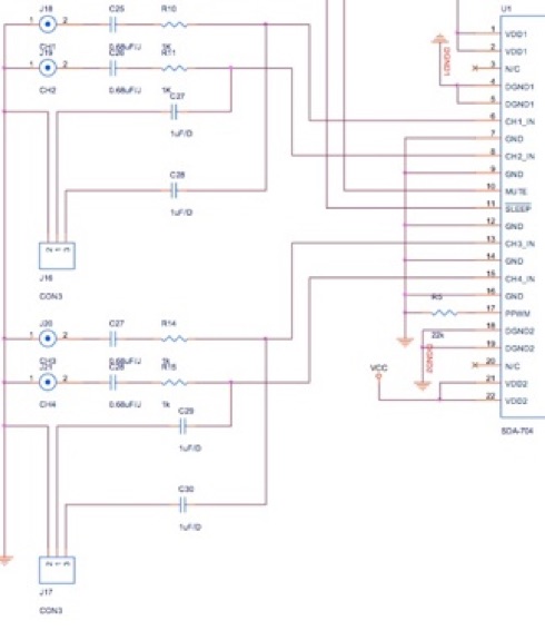
The RCA inputs and the terminal strip inputs have separate coupling capacitors. Since we are using only terminal strips, and the input caps are a bit small, I jumpered the two in parallel, that is, I ran jumpers from J18-2 to J16-3, J19-2 to J16-1, J20-2 to J17-3, and J21-2 to J17-1. That makes the input caps effectively 1.68 uF, and lowers the LF rolloff almost an octave.
Offset adjustment pots are under the heat sink. They are not in the same order as the input jacks. If you’re looking at the RCA jacks 1,2,3,4 the adjusters are in order 2,1,4,3. So if you’re nulling output offset and nothing is


happening, you’re probably turning the wrong pot. It’s safe to run the amp with no load and no signal with the heat sink removed for a short time. Offset also depends a bit on supply voltage, so adjust it using your regular supply.


0.1uF


0.1uF
The amplifier circuit uses paralleled outputs in a BTL configuration, and all outputs are live and at ½ power supply voltage above chassis ground, so no outputs can be tied together, and the speaker negative terminals are hot as are the positive terminals. This isn’t suited to driving headphones or any load that has to be grounded on one side.
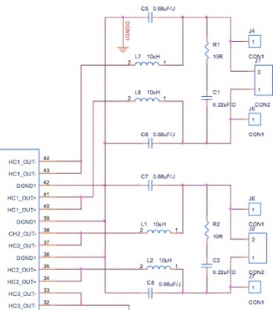
Sure has left out a 0.1uF 50V differential RF suppression cap between output terminals and 0.001 uF caps to chassis at the output terminals.
The amp puts out considerable ultrasonic and RF energy, typically around half a volt centered around 1.7 MHz differential, which is considerably helped by adding the 0.1uF cap across J1 pins 1 & 2, J2, J3, and J11 outputs. That leaves the main RF as about 0.4V at about 700 KHz.
Adding 0.001uF to case ground at the output jacks doesn’t seem to do much. There is some radio & TV interference, but not bad. You can tell the amp is switched on from an AM radio tuned near 700 KHz at a distance of 10 feet, but it certainly won’t disrupt TV reception for your neighborhood like some of the early PCs. I installed the 0.1uF cap on all 4 outputs, and 0.001uF to case on 2 channels. Neither had a measurable effect on response to a 20KHz sine wave signal, and neither was audible listening to music while the cap was switched in / out.
I added a fan on general principles, running very slowly off the 6V winding of the transformer with its own rectifier and filter, so as not to pollute the amp’s supply. The indicator LED likewise runs off that low voltage.
Listening
There is some residual buzz with a small speaker held directly to the ear, but nothing audible at normal listening distance with efficient speakers. Power supply rejection isn’t as great as some topologies, which is to be expected since the power supply is directly switched at the outputs. Noise on the outputs, while considerable, is well above the audio range, and hiss, popping etc. are not a problem. The board is nicely made with surface mount components. Mine is well assembled with one of the output chips evidently reworked by hand. Heat sink compound is properly applied.
Power output is considerably less than Sure’s 100W / chan rating. If you run the amp at absolute maximum voltage with a 4-ohm load well into clipping (Sure says 10%), there might be 100 watts on tap. I’d be more inclined to call it 35 watts / chan @ 8 ohms, 50 W / ch @ 4 ohms. There is headroom above that, but distortion rises steeply.
The amp sounds clean, wide range with deep extended bass and crisp treble, without any boom, crunchiness, or grain. The bottom is full, and the relatively high output impedance lets a bit more of the woofer’s character come out than with a chip amp, for instance. Very enjoyable to listen to, especially with somewhat inefficient speakers like the hemispheres. I found myself spending every spare minute for several days digging through my musical favorites, and that’s the point of building an amp. The Tripath class-D amps are well regarded, and Sure’s board pulls about everything possible out of Tripath’s chip set.
I suspect the somewhat higher than usual solid state output impedance, plus relatively limited subsonic and supersonic response account for the sound quality sometimes described as tube-like. I wonder if the relatively large amount of RF acts like the RF bias of a tape recorder in the magnetic circuit of a loudspeaker, perhaps filling in the B/H loop a bit. Some days I think it could have an effect, and some days I convince myself it’s impossible. A physicist by training, I’m trying to come up with a definitive experiment…
Yet to come, the amp will spend some time in the main system and will have a shot at driving my Quad 57s, a notoriously difficult load. I bought this kit to satisfy my curiosity about Class-D. Sure’s amp merits serious comparison with my latest chip amps, the H/K Citation tube amps, and the big FET amps. The chip amps beat it in every specification and refinement, but it’s plenty good enough. See this page for measurements.

